Friday 23 September 2016

Atterberg Limits, Liquidity Index - Geotechnical Properties of Soil

ATTERBERG LIMITS:

When a clayey soil is mixed with associate degree excessive quantity of water, it's going to flow sort of a liquid.
If the soil is bit by bit dried, it'll behave sort of a plastic, semisolid, or solid material, depending
on its wet content. The wet content, in percent, at that the soil changes from
a liquid to a plastic state is outlined because the liquid limit (LL). Similarly, the wet content,
in percent, at that the soil changes from a plastic to a solid state and from a solid
to a solid state area unit outlined because the plastic limit (PL) and therefore the shrinkage limit (SL), severally.
These limits area unit mentioned as Atterberg limits (Figure one.4):
• The liquid limit of a soil is decided by Casagrande’s liquid device (ASTM take a look at
Designation D-4318) and is outlined because the wet content at that a groove
closure of twelve.7 metric linear unit happens at twenty five blows.
• The plastic limit is outlined because the wet content at that the soil crumbles once
rolled into a thread of three.18 metric linear unit in diameter (ASTM take a look at Designation D-4318).
The shrinkage limit is outlined because the wet content at that the soil doesn't
undergo to any extent further modification in volume with loss of wet (ASTM checkDesignation D-427).The distinction between the liquid limit and therefore the plastic limit of a soil is outlined because theplasticity index (PI), or

LIQUIDITY INDEX:

The relative consistency of a cohesive soil within the state may be outlined by a quantitative relation
called the liquidity index, that is given by
where w in place wet content of soil.
The in place wet content for a sensitive clay is also larger than the liquid limit.
In this case,
LI > 1
These soils, once remolded, will be remodeled into a viscous type to flow sort of a
liquid.

Soil deposits that area unit heavily overconsolidated might have a natural wet content
less than the plastic limit. during this case,
LI <  0


Relative Density - Geotechnical Properties of Soil

In granular soils, the degree of compaction in the field can be measured according to the relative density, defined as
where
The relative density can also be expressed in terms of dry unit weight, or
The denseness of a granular soil is sometimes related to the soil’s relative density. Table 1.5 gives a general correlation of the denseness and For naturally occurring sands, the magnitudes of and [Eq. (1.23)] may vary widely. The main reasons for such wide variations are the uniformity coefficient, and the roundness of the particles.

Size Limits for Soils and Weight Volume Relationship

SIZE LIMITS FOR SOILS:
Several organizations have attempted to develop the size limits for gravel, sand, silt, and clay on the basis of the grain sizes present in soils. Table 1.2 presents the size limits recommended by the American Association of State Highway and Transportation Officials (AASHTO) and the Unified Soil Classification systems (Corps of Engineers, Department of the Army, and Bureau of Reclamation). The table shows that soil particles smaller than 0.002 mm have been classified as clay. However, clays by nature are cohesive and can be rolled into a thread when moist. This property is caused by the presence of clay minerals such as kaolinite, illite, and montmorillonite. In contrast, some minerals, such as quartz and feldspar, may be present in a soil in particle sizes as small as clay minerals, but these particles will not have the cohesive property of clay minerals. Hence, they are called claysize particles, not clay particles.

WEIGHT VOLUME RELATIONSHIP:
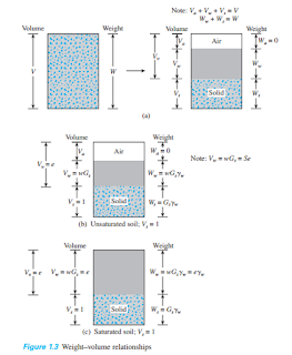
In nature, soils are three-phase systems consisting of solid soil particles, water, and air (or gas). To develop the weight–volume relationships for a soil, the three phases can be separated as shown in Figure 1.3a. Based on this separation, the volume relationships can then be defined. The void ratio, e, is the ratio of the volume of voids to the volume of soil solids in a given soil mass, or
e = Vv/Vs


The degree of saturation, S, is the ratio of the volume of water in the void spaces to the volume of voids, generally expressed as a percentage, or


Note that, for saturated soils, the degree of saturation is 100%. The weight relationships are moisture content, moist unit weight, dry unit weight, and saturated unit weight, often defined as follows:
More useful relations can now be developed by considering a representative soil specimen in which the volume of soil solids is equal to unity, as shown in Figure 1.3b. Note that if then, from Eq. (1.4), and the weight of the soil solids is

The saturated unit weight of soil then becomes

In SI units, Newton or kiloNewton is weight and is a derived unit, and g or kg is mass. The relationships given in Eqs. (1.11), (1.12) and (1.16) can be expressed as moist, dry, and saturated densities as follow:
Relationships similar to Eqs. (1.11), (1.12), and (1.16) in terms of porosity can also be obtained by considering a representative soil specimen with a unit volume (Figure 1.3c). These relationships are


Except for peat and highly organic soils, the general range of the values of specific gravity of soil solids found in nature is rather small. Table 1.4 gives some representative values. For practical purposes, a reasonable value can be assumed in lieu of running a test.

Hydrometer Analysis- Geotechnical Properties of Soil

Hydrometer analysis is based on the principle of sedimentation of soil particles in water. This test involves the use of 50 grams of dry, pulverized soil. A deflocculating agent is always added to the soil. The most common deflocculating agent used for hydrometer analysis is 125 cc of 4% solution of sodium hexametaphosphate. The soil is allowed to soak for at least 16 hours in the deflocculating agent. After the soaking period, distilled water is added, and the soil–deflocculating agent mixture is thoroughly agitated. The sample is then transferred to a 1000-ml glass cylinder. More distilled water is added to the cylinder to fill it to the 1000-ml mark, and then the mixture is again thoroughly agitated. A hydrometer is placed in the cylinder to measure the specific gravity of the soil–water suspension in the vicinity of the instrument’s bulb (Figure 1.2), usually over a 24-hour period. Hydrometers are calibrated to show the amount of soil that is still in suspension at any given time t. The largest diameter of the soil particles still in suspension at time t can be determined by Stokes’ law,


Soil particles having diameters larger than those calculated by Eq. (1.3) would have settled beyond the zone of measurement. In this manner, with hydrometer readings taken at various times, the soil percent finer than a given diameter D can be calculated and a grain-size distribution plot prepared. The sieve and hydrometer techniques may be combined for a soil having both coarse-grained and fine-grained soil constituents.

Monday 19 September 2016

Grain Size Distribution - Geotechnical Properties of Soil

In any soil mass, the sizes of the grains vary greatly. To classify a soil properly, you must
know its grain-size distribution. The grain-size distribution of coarse-grained soil is generally
determined by means of sieve analysis. For a fine-grained soil, the grain-size distribution
can be obtained by means of hydrometer analysis. The fundamental features of
these analyses are presented in this section. For detailed descriptions, see any soil mechanics
laboratory manual (e.g., Das, 2009).
Sieve Analysis
A sieve analysis is conducted by taking a measured amount of dry, well-pulverized soil and
passing it through a stack of progressively finer sieves with a pan at the bottom. The
amount of soil retained on each sieve is measured, and the cumulative percentage of soil
passing through each is determined. This percentage is generally referred to as percent
finer. Table 1.1 contains a list of U.S. sieve numbers and the corresponding size of their
openings. These sieves are commonly used for the analysis of soil for classification
purposes.
the logarithmic scale and the percent finer is plotted on the arithmetic scale.
Two parameters can be determined from the grain-size distribution curves of coarsegrained
soils: (1) the uniformity coefficient (Cu) and (2) the coefficient of gradation, or
coefficient of curvature (Cc).These coefficients are

Cu= D60/D10

Introduction - Geotechnical Properties of Soil

The design of foundations of structures such as buildings, bridges, and dams generally
requires a knowledge of such factors as (a) the load that will be transmitted by the superstructure
to the foundation system, (b) the requirements of the local building code, (c) the
behavior and stress-related deformability of soils that will support the foundation system,
and (d) the geological conditions of the soil under consideration. To a foundation engineer,
the last two factors are extremely important because they concern soil mechanics.
The geotechnical properties of a soil—such as its grain-size distribution, plasticity,
compressibility, and shear strength—can be assessed by proper laboratory testing. In addition,
recently emphasis has been placed on the in situ determination of strength and deformation
properties of soil, because this process avoids disturbing samples during field
exploration. However, under certain circumstances, not all of the needed parameters can
be or are determined, because of economic or other reasons. In such cases, the engineer
must make certain assumptions regarding the properties of the soil. To assess the accuracy
of soil parameters—whether they were determined in the laboratory and the field or
whether they were assumed—the engineer must have a good grasp of the basic principles
of soil mechanics. At the same time, he or she must realize that the natural soil deposits on
which foundations are constructed are not homogeneous in most cases. Thus, the engineer
must have a thorough understanding of the geology of the area—that is, the origin and
nature of soil stratification and also the groundwater conditions. Foundation engineering
is a clever combination of soil mechanics, engineering geology, and proper judgment
derived from past experience. To a certain extent, it may be called an art.
When determining which foundation is the most economical, the engineer must consider
the superstructure load, the subsoil conditions, and the desired tolerable settlement.
In general, foundations of buildings and bridges may be divided into two major categories:
(1) shallow foundations and (2) deep foundations. Spread footings, wall footings, and mat
foundations are all shallow foundations. In most shallow foundations, the depth of embedment
can be equal to or less than three to four times the width of the foundation. Pile and
drilled shaft foundations are deep foundations. They are used when top layers have poor load-bearing capacity and when the use of shallow foundations will cause considerable
structural damage or instability. The problems relating to shallow foundations and mat
foundations are considered in Chapters 3, 4, 5, and 6. Chapter 11 discusses pile foundations,
and Chapter 12 examines drilled shafts.
This chapter serves primarily as a review of the basic geotechnical properties of soils.
It includes topics such as grain-size distribution, plasticity, soil classification, effective stress,
consolidation, and shear strength parameters. It is based on the assumption that you have
already been exposed to these concepts in a basic soil mechanics course.